Final


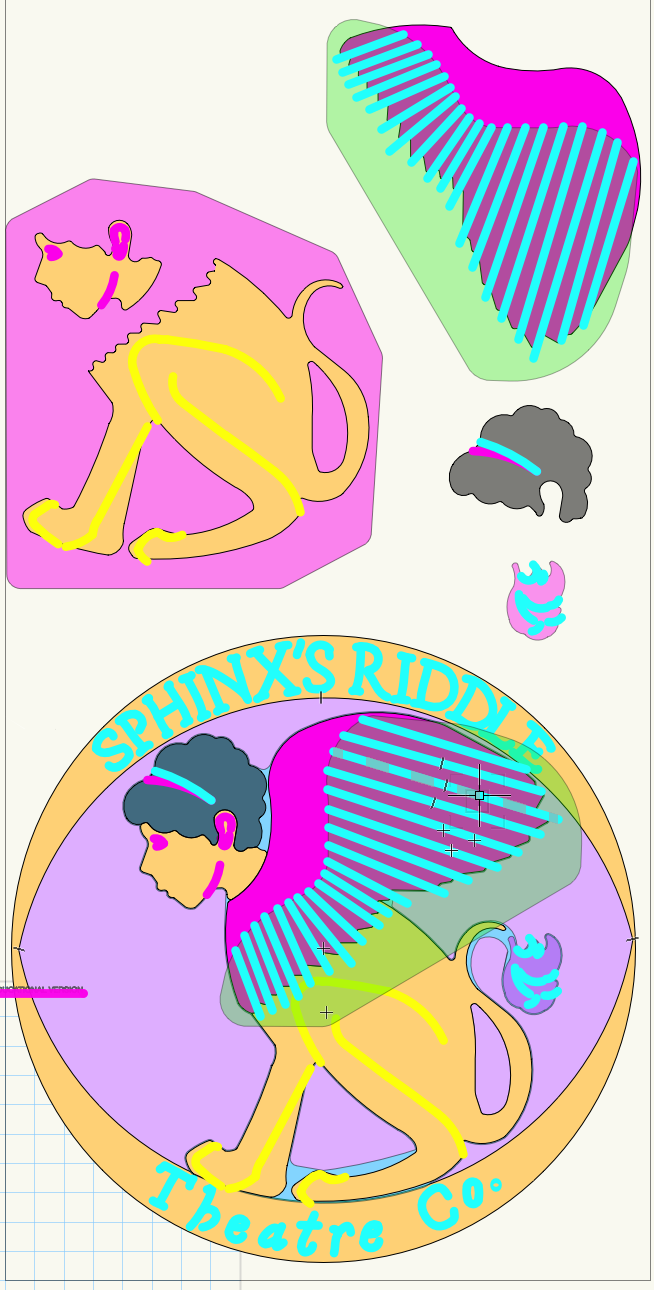
This is the logo for my partner’s theater company in Denver.

 
logoWithYellow.png
 

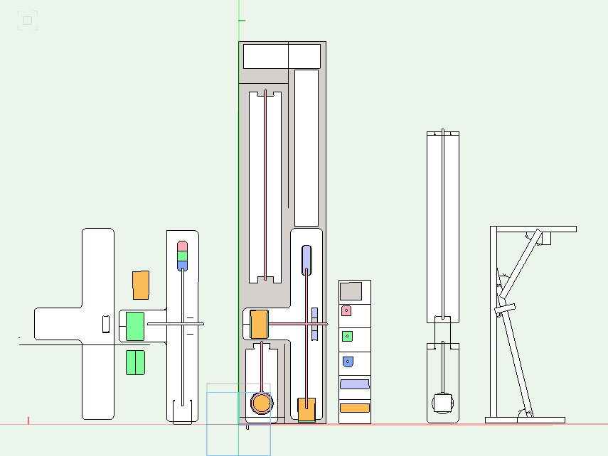
I’m hoping to make a bas-relief replica of that logo that the company can hang up at events. I imported the file into Vectorworks, then traced it and separated out layers that could be cut out at different depths with different bits.

 
Screen Shot 2019-03-13 at 7.23.29 PM.png
 

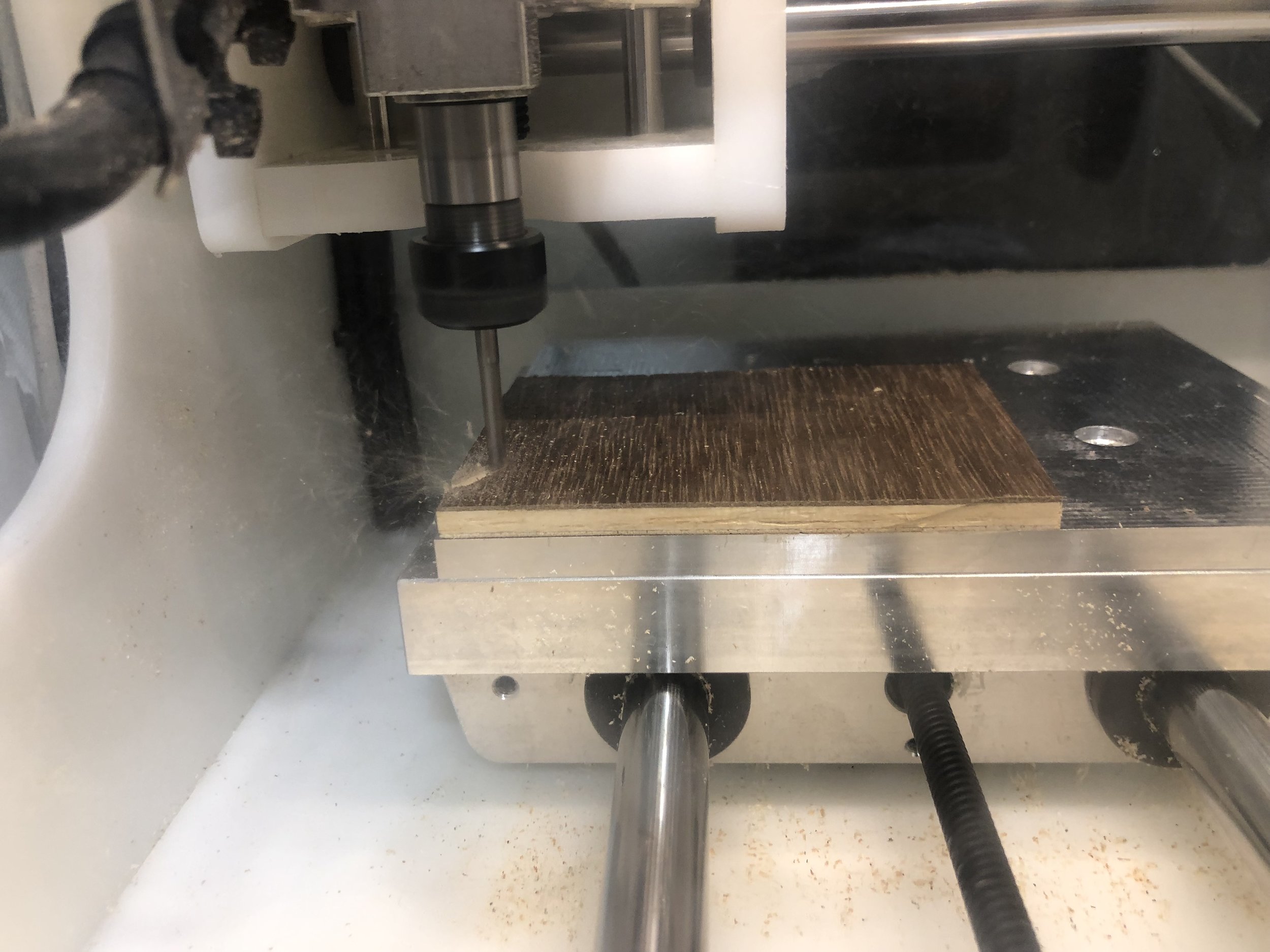
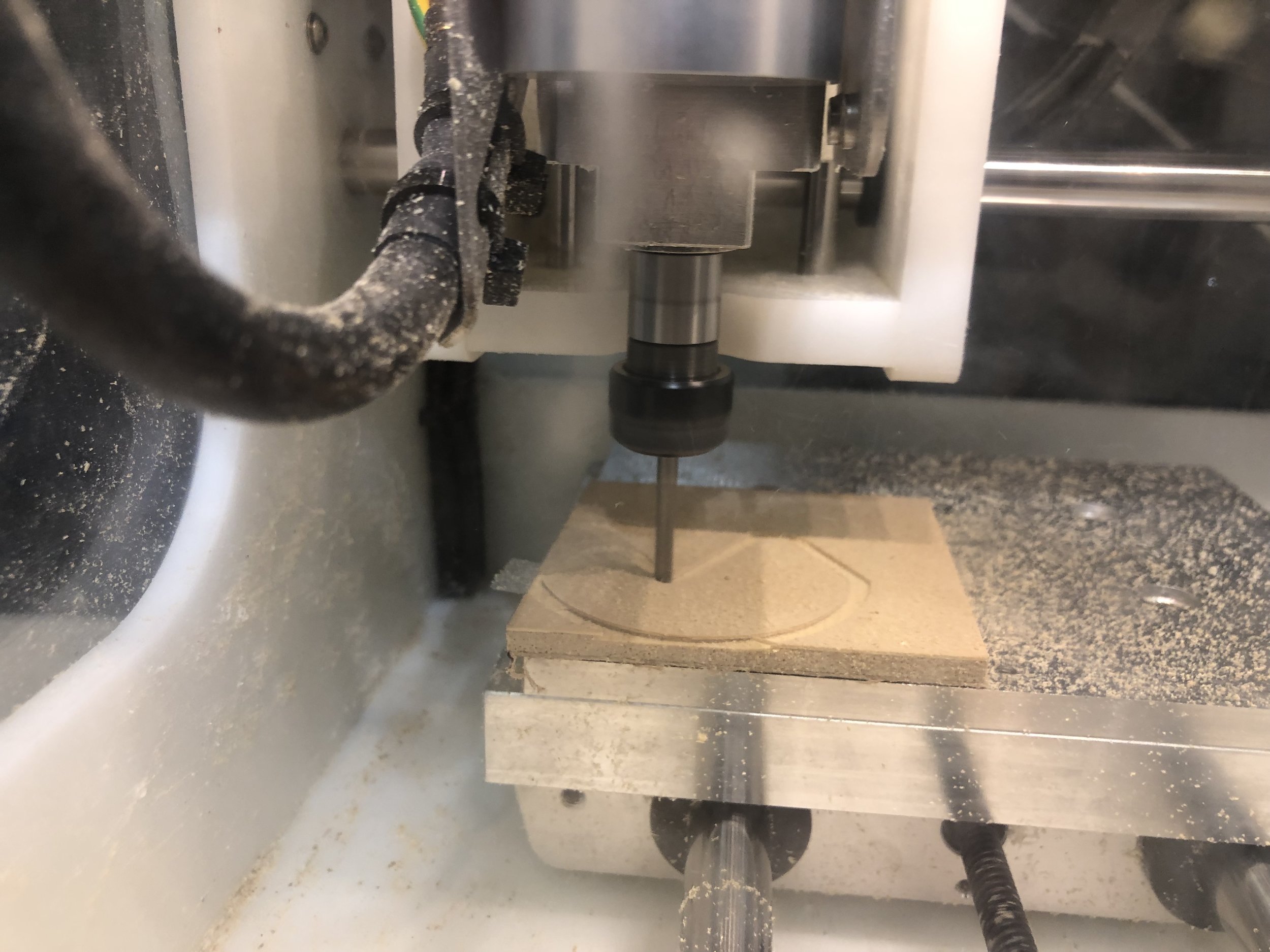
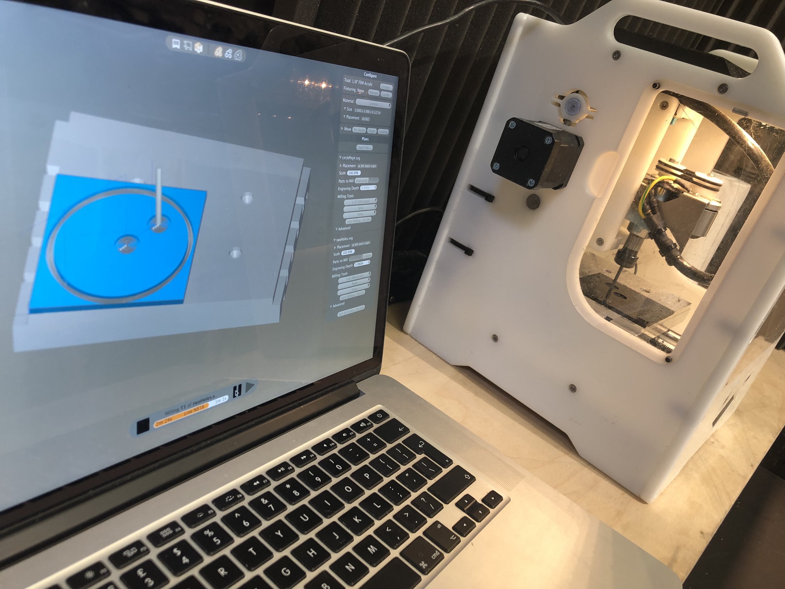
After an awfully long time on the MasterCAM machine exporting out each layer, I began the work of cutting out everything with the CNC router.


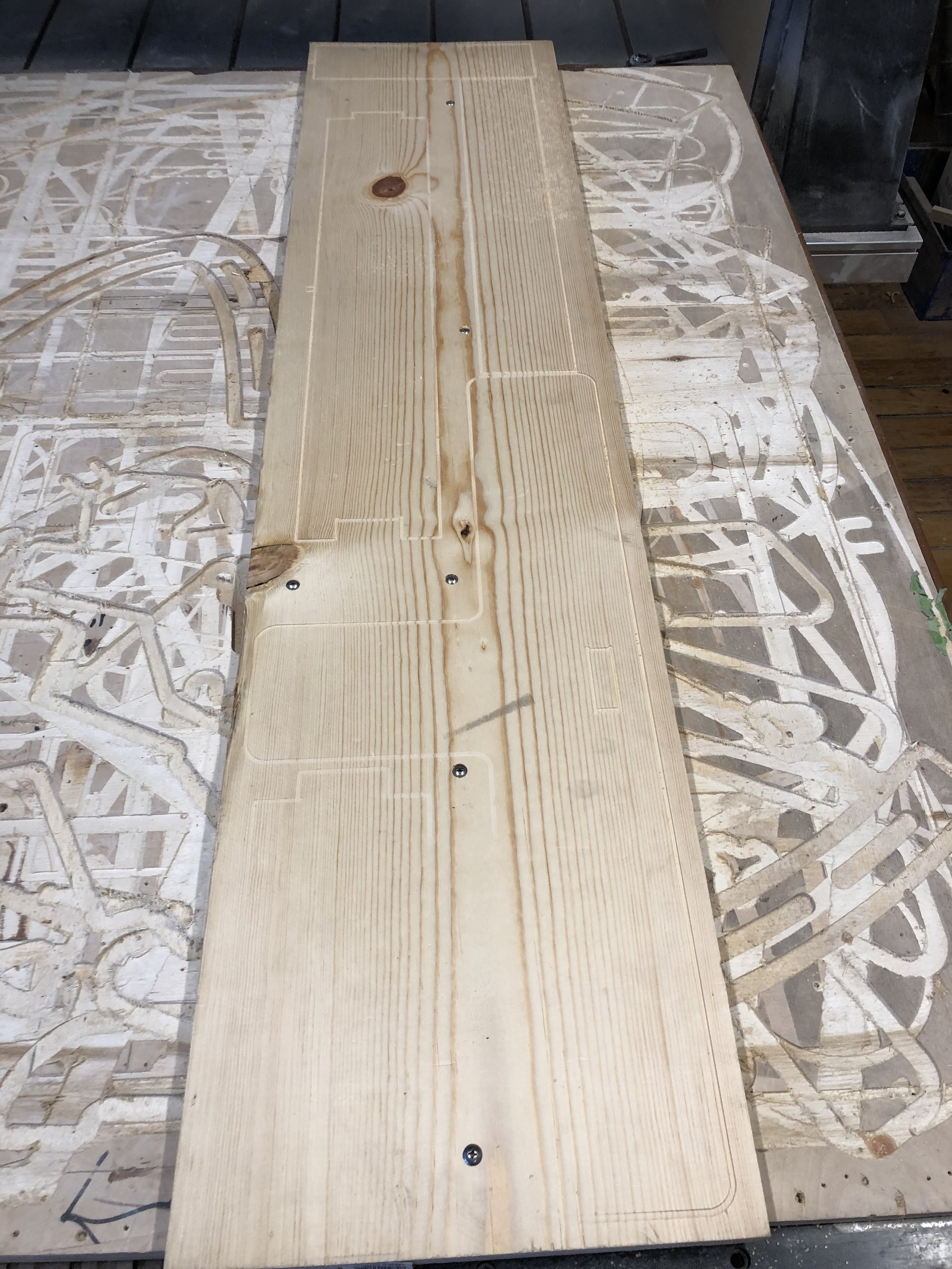
I started by cutting out the larger circle, then I used the ½” bit to pocket out the skin and hair areas at the proper depths, then used a special bit to cut out the finer lines.

 
IMG_0910.JPG
 

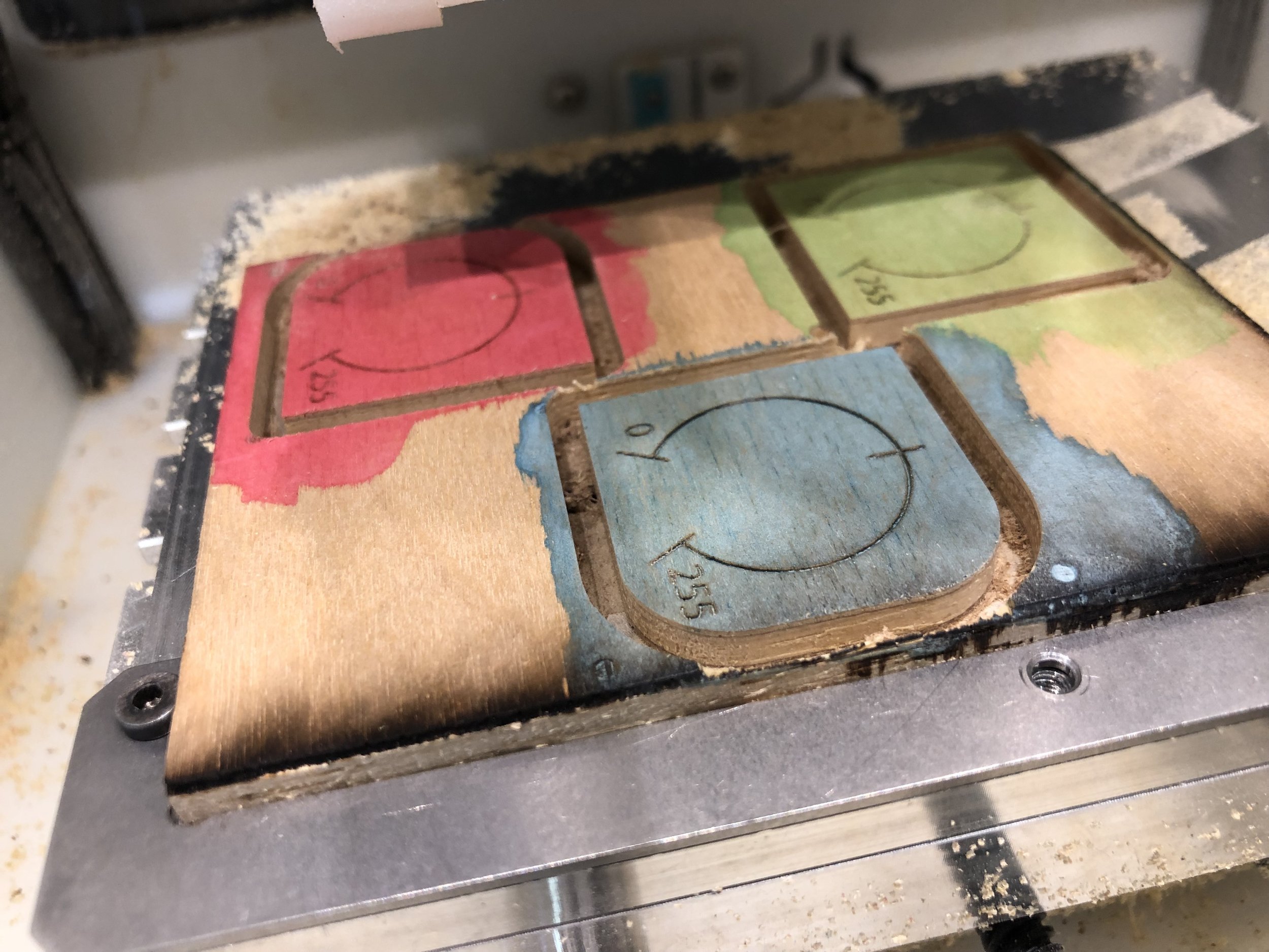
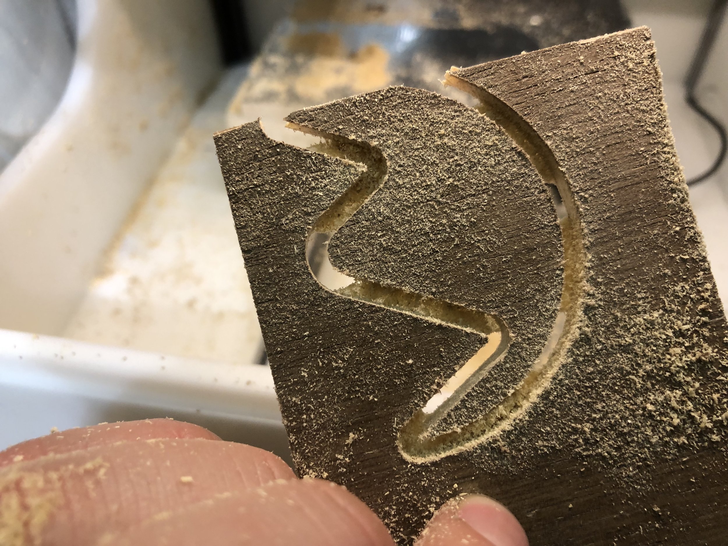
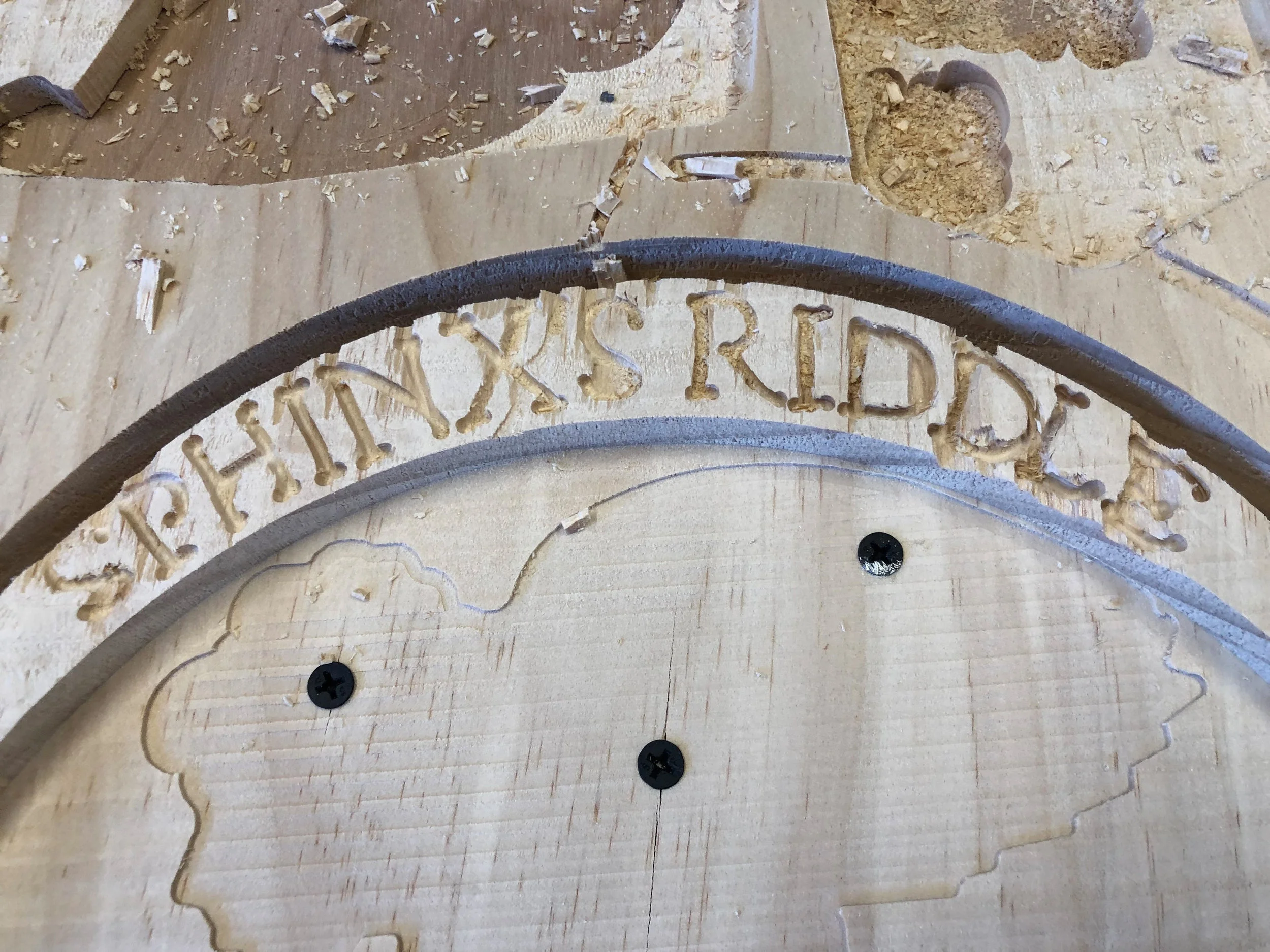
When I was about one cut away from finishing, I realized I needed to make a small adjustment on the z-Axis. I paused the machine, re-zeroed, then clicked start. Nothing happened the software was stuck. I clicked “reset,” thinking that maybe that would fix it, and the mill went back to zero, plowing through much of what I had already cut.

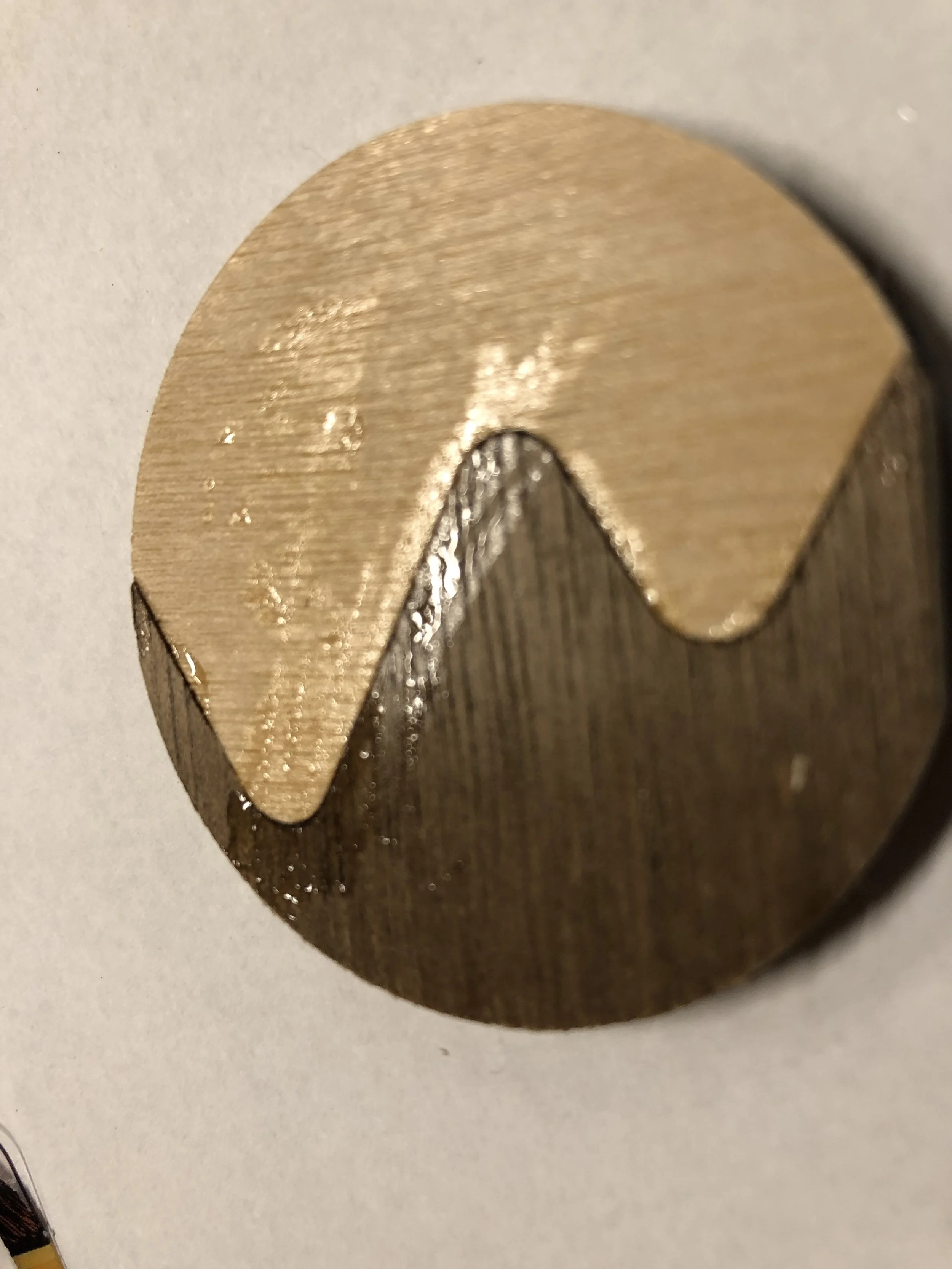
I tried to fix it by pocketing down the large circle to below where the gouge had happened, but it left the whole thing a lot uglier than it had been before.

 
IMG_0914+3.jpg
 

I needed to cut my losses on the big circle background. Fortunately, I still had all the pieces cut out for the sphinx itself, which is what I’ll be focusing on in class tomorrow. I sanded each piece down until they were smooth, then took some different shades of wood stain to it.

 
IMG_0923 2.JPG
 

After some stain and tung oil, I have my sphinx. I think it’s looking pretty good, and I’m excited to rebuild the outer circle so that everything fits together.

 
IMG_0925.JPG
 

Looks like everything fits! Time to glue it together and hang it up.

Puppy included for scale.

Puppy included for scale.

Joinery

My first go-round with the CNC was a fairly complex project. It was a steep learning curve, but ultimately, I was pretty happy with how it worked out. The one big problem with it (outside of some wiring problems that fall outside of the scope of this class) was that a support brace that I had built for it fell apart on the subway ride home.

This wasn’t a surprise – the brace wasn’t elegantly designed and was shoddily glued together. I was left with a camera stand that, while functional, sagged a little. This made me fairly nervous for long-term use (I don’t want this thing breaking and destroying my camera). So for my joinery assignment, I decided to fix this problem.

The original brace consisted of two legs that were glued together at an angle. What would be a better way to make these two pieces join?  Well, honestly after looking through some of the options that were recommended on the site, it seemed like the best option was just to cut it out as one piece


I designed a new brace based on some of the original sketches, this time arcing them a little bit just for some flair. I made some pockets at the ends, so that the piece would be left with some tabs to slide into the pockets on the original piece.


The new bracket fits in nicely, and friction holds it in well enough that it doesn’t need to be glued.


Simple, functional, done.

Week 4 Documentation

I wanted to solve a problem with this project. My problem looked like this.


This is a camera mount that I’ve been using as a pencil-tester for hand-drawn animation. While it might be a good example of valuing function over form, I’m a little surprised that the whole thing hasn’t fallen over yet. So I set out to make a new one.


I know that the purpose of this project was to keep it simple, but this is something I wanted to use for an upcoming midterm, so I needed to go a little farther on this one.

I screwed down a 4’x11” piece of plywood, and I ran a rough trace of my contours just to be sure that everything would fit.


Well, that’s interesting. The surface is uneven in a way that the bit was cutting into the wood at the top end, but not on the bottom. That wasn’t totally unexpected, though, given how big the piece was. Precision in the z-axis wasn’t the most important thing for me on this project, so I just went ahead.

 
IMG_0871.JPG
 

I cut the whole thing with an 8-inch bit, so it took a while. Sorry if anyone else wanted to use the CNC on Sunday. I cut out the pockets first, making sure that elements were fitting properly as I went


Once the pockets were dug, I screwed in each piece and cut out the contours. By the end of it, I didn’t have a whole lot of scrap left, but I did have a pretty nice-looking camera mount.

 
IMG_0878.JPG
 

I had wanted to add in some sliders and knobs to control a lamp that I had placed in the top, so I took some of the elements that I had been using to make pockets in Vectorworks and modeled wooden plates from them. I then made some smaller plates for knobs and sliders on the Bantam.


And ultimately, now I have an animation stand on my desk. It’s still a bit of a rough draft – the interfaces probably need to be re-soldered and the plates don’t exactly fit in (I think I might make a refined version of the base for my next CNC project), but overall this was a fun process and I’m excited to be able to make some more cool stuff with the CNC.


Week 3 Documentation

Work for my project started on Friday, when I put in an order for two 6”x6” sheets of 1/8” thick aluminum. I hadn’t cut metal on the Bantam before, and I was excited to give it a shot. I was out of town for a few days, so I wouldn’t be able to get my material until Wednesday morning. In the meantime, I put together a couple of puzzle pieces that would hopefully be able to fit together in a fun way.

 
Screen Shot 2019-02-20 at 4.25.52 PM.png
 

Unfortunately, 6”x 6”, the smallest size I found on McMaster, was larger than the spoiler plate on the Bantam tool, and I couldn’t get it to work. I asked about cutting it down in the shop, but apparently 1/8” is too thick to be cut by anything available on the floor.


In the future, I’ll be sure to order thinner sheets of aluminum. Right now, it’s time for a little improvisation.

 
IMG_0842.JPG
 

I had some scrap leftover from my final last year that I thought could work well. It has two different colors on the front and back, so if create two pieces and flip one of them, it should make for a fun design.

 
IMG_0845.JPG
 

The pieces are quite a bit smaller than what I had originally made, so I needed to redesign the Vectorworks file. 

 
Screen Shot 2019-02-20 at 4.54.39 PM.png
 

And here we go! I milled piece with the tape on the light side, then flipped the wood to mill with the other side facing up on the other piece.

IMG_0851.JPG

With each piece, the mill was actually so precise that it didn’t cut the double-sided tape loose, making the pieces much easier to remove.

IMG_0852.JPG

After cleaning out the mill, it’s time to glue these pieces together.


While I acknowledge that epoxy might be a little overkill for a tiny wood piece like this, I hadn’t used it before and I wanted some practice with it before using it on a bigger project. Plus, I had already bought it and I really didn’t feel like waiting for wood glue to dry.


That’s… not the prettiest glue job in history. Let’s see what some sandpaper can do.

IMG_0856.JPG

That doesn’t look bad!

Week Two Documentation

I had some leftover acrylic from last semester, which was pretty easy to turn into a nice square piece for the Bantam mill for this week’s assignment.

After an extremely helpful meeting with Ben in the afternoon, I was ready to cut and engrave this small piece into a simple part using the Bantam mill. I figured the simplest thing I could do with my 3”x3” piece would be to cut a circle, with one smaller circle engraved in the center to act as a hub, and one set off-center where a crank or something could be inserted.

 
twoHoles-01.png
circle-01.png
 

And once those two SVG pieces were loaded into the Bantam program, there wasn’t a whole lot left to do but let the mill run.


I let the machine engrave the smaller two holes first then I had it cut out the larger piece.


When the machine was finished, I pried the piece up off of the bed, and took a look.


A small film of plastic was left over on the edge from where the machine didn’t quite cut through, but that smoothed out pretty easily with a little bit of sandpaper on the corner.

 
IMG_0833.JPG
 

It’s not the most practical piece in the world, but I feel comfortable with the Bantam mill now, and I’m excited to start thinking about how to use this process for more complex projects.

Week One Documentation

Prior to this week’s assignment, I had never used a router before. I didn’t quite know what to expect in terms of difficulty, but ultimately it was a pretty straightforward process, slowly ratcheting up the bit with each pass until the piece was finally done.

 
Picture1.png


And I think it wound up looking pretty good. Take a little sandpaper to the edges, and I had a nice-looking little circle with a segment cut out of it.

 
Picture2.png
 

 And let’s just check it against the example in the project to be sure it looks right…

 
Picture4.png
 

Oh.

Apparently, we were meant to be focusing on the outside part of the circle.

Which I didn’t quite understand until I saw the final segment of the assignment in which we were instructed to cut out the 1’x1’ square from the original piece of plywood. And this is a bit of an issue for me, given that as I was focused on the inside piece, I had let my router go a little way into the outside of my plywood.

 
Picture5.png
 

Time for some coarse sandpaper!

 
Picture6.png
Picture7.png
 

So now I have a fairly nice looking circle segment, and a somewhat odd-looking part cutout of a 1’x1’ piece of plywood.

 
Picture8.png
 

Ultimately this project taught two equally valuable lessons- the first being an intro to the router, and the second on the importance of understanding the assignment before starting on it.