Blog 11-27

IMG_0484 copy.jpg

Whew, it’s been a crazy few weeks. Between spring registration, Thanksgiving, and some significant projects in other classes, I haven’t been able to make as much progress on my PComp final as I had hoped. I don’t have a whole lot to present this week. It’s a bit of a shame, because I feel like the input I’ve gotten from my peers so far has been fairly helpful. Fortunately, though, I’ll have a couple more chances to present my project between now and the final presentation. I’m combining my ICM and PComp finals, so my ICM class next week will provide another much-needed user testing phase.

The most I can present at the moment is my daily schedule. I’m looking at this now and I’m nervous for how to get this done, but I still think that it’s doable.

Daily Schedule

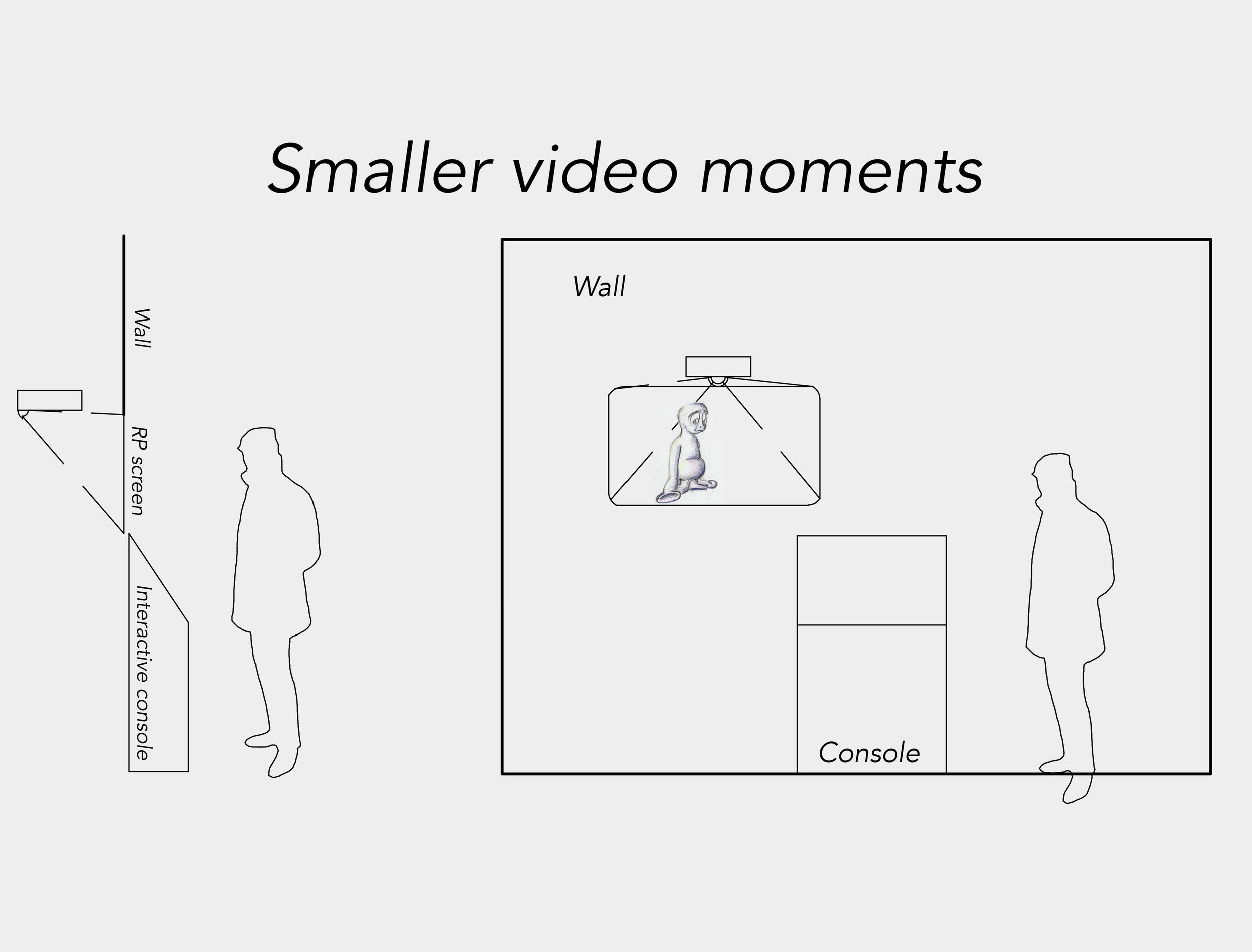
 Wednesday 11-28 – Talk through concept with class, ask about triggers. Tubing, acrylic, and lumber need to be purchased.

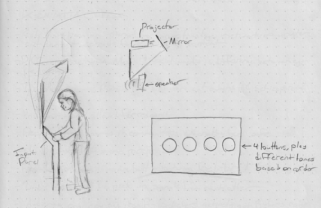
Thursday 11-29 – Syphon sketch into MadMapper needs to be up and working. Plan out any additional animation needed

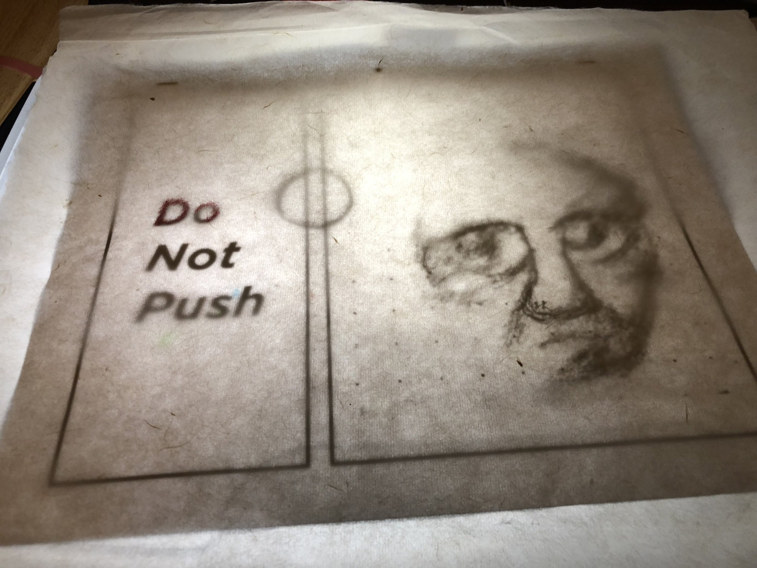
Friday 11-30 – Finish CAD sketch. Program triggers for processing, send through MadMapper into secondary monitors. Finish Illustrator drawing for monitor mask.

Saturday 12-1 – Construction day. Timber needs to be cut and assembled. Acrylic needs to be cut on the laser cutter.

Sunday 12-2 – Off day to work on other projects.

Monday 12-3 – Assemble and test what you have for ICM next day.

Tuesday 12-4 – Present for ICM. See if concept is clear, ask what can be improved. Incorporate advice into project for PComp tomorrow.

Wednesday 12-5 – Present for PComp. Take in advice for concept and incorporate into project. Re-design as needed.

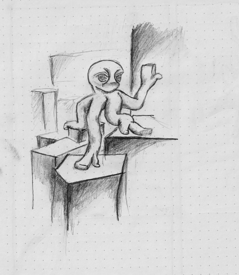
Thursday 12-6 – Re-arrange triggers as needed, animate creature as needed.

Friday 12-7 – Incorporate new animations into design.

Saturday 12-8 – Program LED strips in processing. Plug transistors into board and get them working for lighting control.

Sunday 12-9 – Off-day to work on other projects.

Monday 12-10 – Finalize project for ICM tomorrow.

Tuesday 12-11 – ICM final presentation. Take any input from ICM, finalize for PComp presentation.

Wednesday 12-12 – PComp final presentation.

Materials –

-       Wood and particle board to build stand for computer/monitor

-       Brackets and screws for stand

-       Paint for stand?

-       Tubes to represent characters feet

-       LED strips to go into tubes

-       Acrylic for monitor mask

-       Projector – must be able to rent from ER

PComp Final - Proposal

I recently put together a proposal for a fairly complicated installment in an escape-room style walk-through theatrical show.


It’s not practical to think about all of it for this project, but I wanted to see if I could simulate a small piece of it here. I’m hoping to create a panel of buttons that will constitute my installation’s input. Two screens will constitute the installation’s output.

 
Scan.jpeg
 

if the correct input is received, an animated character will move, similar to what happened with my PComp midterm.

 
Scan 1.jpeg
 

This time, however, instead of a simple biting movement, the creature will leap out of the screen and appear on a second screen behind the user. The user will be made aware of the video behind them because of sound coming out of a speaker.

As of right now, I feel like this should be an achievable and exciting project. My biggest concern right now is being able to control the lighting in the space, which would be necessary to pull off the illusion that I’m hoping to achieve. On those same lines, my professor has said that “walk-through experiences” that require control of the space are tough to pull off, so I’m curious to hear suggestions.

PComp Midterm

I wanted to test out a trick where a drawn image could be made to come to life.

I started off with an image on paper


Made some good old fashioned hand-drawn animation to go underneath it -

Face_001_02_X1_0008.jpg
Face_001_02_X1_0015.jpg


laser-cut a sheet of acrylic to hold my paper sketch on top of my monitor -


and I got my button to trigger Isadora thanks to some help from the Isadora forum.

Next I made some modifications to my home lamp so that it could be controlled through the breadboard…

 
56204971568__44455293-B40B-4EF3-A64C-BF96FA02BAA2.jpeg
 

And we’re about good to go!


My girlfriend shared this with my after seeing my project. I had to include it here.


Week 6 Documentation

For this week in Physical Computing, I needed to modify an existing p5 sketch using an input from an Arduino. I chose to use my sketch from the second week of the class, which happens to be my favorite because it’s based off of this lovely lady:

 
I like my dog. Don’t judge me.

I like my dog. Don’t judge me.


The original sketch followed a ball around the screen, and her tongue slowly dropped down at the beginning of the sketch.

 
Screen Shot 2018-10-16 at 2.37.48 PM.png
 

It always kind of bugged me that her tongue just dropped down and stayed there, like she had just lost control of it or something. I thought that using a potentiometer to control her tongue would be a good idea.


Week 5 Documentation

I mentioned in my last post that one of my goals for this class will be to create a programmable camera mount to be used alongside Dragonframe for my first animation project in the second half of the semester. Given what I’ve seen of class schedules from previous years, I think that it would need to be ready by Halloween for a project due on the 7th (assuming that most classes follow the same schedule). Which means that, in addition to the PComp midterm, I need to take opportunities each of the next few weeks to take steps towards that goal. It’s going to be a challenge, but I’m hoping I can make it work.

Long term, there are three big things that I need my device to be able to accomplish –

1.     It needs to be able to take discreet, incremental steps based on a specified input run through a mathematical function.

2.     It needs to be able to transfer that input to a 360° motor, which has the ability to do real mechanical work.

3.     That motor needs to be able to move an entire camera along a single axis.

I don’t know how steps two and three are going to work right now, so I’m going to focus on step number one. I want to make sure that I have the programming ability to make it do step one. I’m going to keep a similar setup as last week, but instead of using an FSR to control the Servo I’ll be using a digital input. (The assignment for this week was to “review any of the labs that gave you trouble in the past,” so I figured I had some flexibility to do some work for a bigger project. Let’s call this Lab 2, but with a servo instead of a speaker.)

 
IMG_0370.jpg
 

Ok, so just to get back roughly to the place where I left last week, let’s modify this code to look for an input that I give it.


So I just changed what had been an analog in from my FSR last time to an integer that I set manually, which I chose to call “stepValue”. Assuming that I wanted my stepValue to range from ten (set as an integer variable at the top of my code), then that value would map to a servo angle. In this case, mapping to an angle of 161.

Now for the function part. Right now, the motor moves in a straight line from 0° to °180. I want it to be able to “ease in” to its final position, similar to using a Bezier curve in After Effects to map variables. So instead of the curve of angle over time (or in this case steps) looking like this

 
Screen Shot 2018-10-09 at 2.36.31 PM.png
 

I want it to look like this –


So there are a couple of things that I need to figure out. First, how does a program like After Effects even make a function like this? And second, how do I translate that function to use with an Arduino?

For the first question, I checked on an online forum. The answer that I found was….

 
Screen Shot 2018-10-09 at 2.44.36 PM.png
 

A little more complicated than I had hoped it would be. I might need a refresher on my high school calculus. I’m sure Wikipedia can help.

 
Screen Shot 2018-10-09 at 2.59.28 PM.png
 

Um, I’ll just keep reading and maybe it will start to make sense…

 
Screen Shot 2018-10-09 at 2.59.20 PM.png
 

Ok, this ain’t happening. I can’t write this myself. Honestly, I don’t even know what I’m looking at when I check GitHub for answers. Fortunately, p5 has exactly the function that I’m looking for.

 
Screen Shot 2018-10-09 at 3.08.33 PM.png
 

And extra fortunately, the subject of this week’s videos was all about using serial communication to communicate across platforms. If we write some special fun code to get us an output along a Bezier curve in p5. So now I need to create a node in p5 that travels along a Bezier given an input -

 
Screen Shot 2018-10-09 at 3.41.25 PM.png
 

And here is where I hit a snag. I can get p5 to draw the Bezier, but I can’t get it to output the y-value for a given x input. I think for today I’ll just have to use a simpler formula that I arrived at with the help of an online graphing calculator

 
servoAngle = angleMax - (angleMax / (principle ^ stepValue))

servoAngle = angleMax - (angleMax / (principle ^ stepValue))


Which works well when plugged into the Arduino –

 
Screen Shot 2018-10-09 at 4.58.47 PM.png
 

So now I have a couple of accomplishments, and a couple questions. I have a device which successfully takes a function of my own making and translates it to the outside world. But I need to be able to generate a more complex function input in p5, and I still need to be able to transfer that to the Arduino’s input. And after that, I need to translate that into something that can move. Moving slowly, but moving forward.

Week 4 Documentation

I’ve been itching to get into the Servo motors for a while now. One thing that I’m hoping to accomplish with this class is to create a moveable still camera rig whose position can be easily programmed in for use in stop-motion.  So, for this assignment, I figured I’d dip my toe into that particular pool by doing Lab 4.

I started with by setting up all of the sensors the way that they said to, using a force-sensitive resistor that I had borrowed from the lab.


The next step, of course, is to calibrate the thing. I left the resistor untouched and took a look at what the computer read.


Goose eggs. Good. Now let’s see what happens when I push down hard with my thumb and forefinger.

 
image3.png
 

Maximum is in the 860 range. So let’s map our inputs to that range and write to the Servo.

Ok, that should do it. Does it work?


I shot vertical video. Sue me.


I count that as a success.

Week 3 Blog

I remember when self-checkout machines were first introduced, they caught a lot of flak.


(There are obviously a few things about this video that haven’t aged well)


I only realized how much I had come to like them when I came to New York and was kind of annoyed that most stores didn’t have them. I honestly wish I didn’t feel that way. I wish I valued a checkout system that forced at least a small amount of in-person interaction into my shopping experience and kept people employed, but I don’t. I would rather deal with a touch-screen. The machines are winning.

The closest thing to a grocery store automated checkout that I was able to find was at the Regal Cinemas at Union Square. It’s not exactly a grocery store checkout, but I figured it’s close enough.


I’ve been meaning to see BlacKkKlansman for a while, so I figured I’d take the opportunity to pick up a ticket for Thursday.

 
IMG_0327.jpg
 

The first thing I notice is just how easy it is for me to make an impulse buy with this system. I know from experience both as a retail consumer as a retail employee that that’s half the point of having these things at all. Interacting with a machine is a lower barrier than interacting with a human being to get you to buy something.

 
IMG_0329.jpg
 

I’m taken through some more screens, each of which only has a few options to choose from. Big buttons are displayed to make it clear where I’m supposed to hit to get to the next screen.

 
IMG_0332.jpg
 

And this is the screen that took me the most time to complete. As I watched other people using the machines, it was the screen that they took the most time at, too. I found this interesting because this is the sort of thing that the machine can, without a doubt, do better than a human clerk. An easy to understand graphic of where you’ll be sitting. So why does this moment take the longest?

The answer became clear the more I watched other groups buying tickets. The delay wasn’t caused by the machine, it was caused by the people. Couples and groups came in mostly knowing what movie they wanted to see and when. But during seat selection, the process had to stop as they talked it over as a group.

Which, to me, is what gives me some hope about the whole automated check-out thing. Because the interaction between human and machine in this instance isn’t that.. well, interactive. It’s more like a series of switches than a thoughtful conversation. The conversation doesn’t “sparkle,” to quote Chris Crawford.

But it doesn’t need to. The best thing that this machine can do is get out of the way as quickly as possible so that the interaction that actually matters, the one between friends out to see a movie, can happen with minimal interference.

Plus it got me to buy a movie ticket without having to take the time to talk to anyone. A blessing and a curse, I suppose.

Week Three Documentation

For this week’s class, I decided to modify my light meter from last class using the microcontroller. Last week, one thing I was hoping to do with my light meter was to make it easier to read by having multiple lights light up as the amount of light hitting the meter increased. This seems like a much better interface, because it can measure specifically when light hits a specific point, and gives the user more concrete feedback than just how much electricity is flowing through a single LED. There was a certain irony in the fact that my last project was designed to tell the user how much light was hitting a sensor and in order to read it they would need too… look at how much light was coming out of an LED.

Thankfully, there was a video example in the class resources of people doing something similar to what I was hoping to accomplish using a photocell resistor. My first step was to connect the output of my light meter into the analog input of the Arduino. I did this by allowing one track of current to flow through a resistor into ground, and one track to flow through the detector into the A1 pin of the Arduino. The less resistance the detector gave, the more current would flow into the A1 pin.

IMG_0302.jpg
Screen Shot 2018-09-22 at 10.53.59 AM.png

Next, I needed to establish some “if” statements in my Arduino code to divide the amount of electricity it was receiving into six discrete categories (six was chosen somewhat arbitrarily), and if each category was met, to send a “high” signal to one of six pins on the actual board.

 
Screen Shot 2018-09-22 at 1.16.38 PM.png
 

I chose to define each level at the beginning of my code based on what I read from the outside world. Level one was chosen by when my lights were turned off but the device was left uncovered reading ambient light. Six was chosen based on how much input it read when I shined my iPhone flashlight directly on it. Three was chosen when my room light was turned on, but it received no additional light.

Next, the actual board needed to be set up. I set up the same system for six LED’s hooked into the various pins, each with its own input and output coming from the board, and resistor to keep the light from burning out. Before attaching the lights to any of the output pins, I tested  each of  them on the regular positive and ground strips on the breadboard.

 
IMG_0312.jpg
IMG_0313.jpg
 

And they all worked! (I should mention that after testing, I did realize that I could have set this up using just one resistor to connect to a line of the breadboard and connect the lights in parallel downstream of that, but this was working and I didn’t want to mess with it.) I set it up to receive input from their respective output pins on the Arduino.

 
IMG_0314.jpg
 

Ok, everything is set, let’s see if this works…


Excellent! Now it’s time to trim down the legs on the LED’s to make it a little less ungainly.

 
IMG_0322.jpg
 

And there we have it! Light meter whose readout is calibrated with a microcontroller and can be read with an array of LED’s.